Impellers (also spelled impellors or impellars) are rotating devices designed to alter the flow and/or pressure of liquids, gases, and vapors. Impellers consist of various vanes — often blade-shaped — arranged around a short central shaft. When the shaft and vanes rotate, they suck in fluids or gases and impel them out the other side. The image below illustrates basic impeller operation.
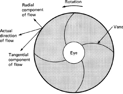
Basic theoretical impeller design, showing the eye (shaft), vane assembly, and flow direction.
Image credit: McGraw-Hill via The Free Dictionary
Impellers are typically found in — and are integral components of — pumps, agitation tanks, washing machines, and other devices requiring fluids or gases to move in a specific direction. The image below shows the position and function of an impeller in an impeller pump. In this example, fluid enters through the orifice on the right and is moved through the pump using a combination of suction and pressure until the fluid is moved through the output orifice on the left. Note that this particular impeller is designed to rotate clockwise unlike the one in the image above; this rotation coupled with the design of the vanes causes the pump impeller to move fluid in a roughly clockwise direction.
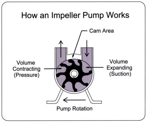
Image credit: BoatTest
Impellers vs. Propellers
At sight, impellers appear very similar (or even identical) to propellers, and the two are often used interchangeably in the fluid power industry. Indeed, the two base terms involved — propel and impel — are both defined as "driving or moving forward." In industrial applications, however, the two are used to describe two different devices which drive two different objects or substances.
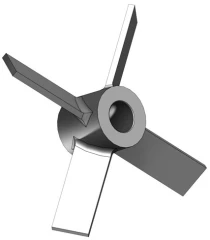
Propellers commonly refer to devices which move an attached object. For example, a ship's propeller moves the ship itself forward or backward. Impellers, on the other hand, are designed to move the substance — fluid or gas — passing through it without moving the object it is attached to.
Applications
While all impellers consist of similar design elements as described above, they may perform slightly different operations depending upon their intended application.
Impellers in Pumps
Impellers are integral components in centrifugal pumps and vacuum pumps, among other pumping devices. Pump impellers rely on Bernoulli's principle — which states that an increase in fluid velocity is accompanied by a decrease in pressure or potential energy (and vice versa) — to operate.
When fluid or gas media enters an impeller pump, it becomes trapped between the impeller vanes and the pump wall and increases in velocity as it moves from the impeller eye (center) toward the outside diameter of the impeller. Once the media reaches a certain point nearest the outside diameter, it abruptly decreases in velocity and experiences an equal increase in pressure (according to Bernoulli's principle). The media becomes even more pressurized as it is discharged from the impeller and out of the pump orifice. Based on these principles of operation, it can be discerned that a pump impeller's rotational speed (affects velocity) and vane height (affects pressure and the possible formation of a vacuum) largely determine the pump's output pressure and flow.
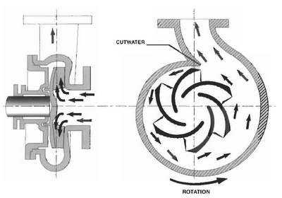
An impeller as a component of a centrifugal pump.
Image credit: Engineer's World
Impellers for Mixing
Impellers are frequently used in agitation tanks as a means to mix fluids and slurries. Mixing impellers typically employ an open design and are fitted to a central shaft which is placed in the center of the tank.
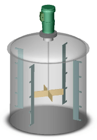
An agitation tank with a central radial impeller. Image credit: Post Mixing
When fitting a tank with an impeller, it is important to choose between axial and radial flow types. (See Flow Direction below for more information about flow.) Radial impellers — which typically have rectangular vanes — are used when the tank media is excessively viscous or consists of two immiscible materials. Radial flow impeller types include:
- Radial Flow Anchor - An impeller designed for mixing higher viscosity products. An anchor is normally "U" shaped, and follows the contour of the tank. Anchor impellers are specifically designed to fit the process. Anchor impellers are used to sweep the entire peripheral area of a tank - both walls and bottom.
- Radial Flow Paddle - Used for mixing. Impellers that convey the media outward to the side of the tank. Larger slow-speed impellers, with two to four blades are known as paddles. Paddles are used at slower speeds often used for large scale mixing of solid/ liquid suspensions.
- Radial Flow Turbine - Used for mixing. Turbines are the multi-blade type Impellers that convey the media outward to the side of the tank. Turbines, which come in a variety of types, provide excellent circulation of fluid throughout the mixing vessel.
Axial impellers are suitable for homogenization and mixing which requires bulk motion. Axial flow pitched blade impellers have one or more paddles. They convey pumped media in the direction along the revolving axis of the impeller. Axial flow impellers are used at high speeds to promote rapid dispersion and are used at low speeds for keeping solids in suspension.
Power Number
Power number is a value specific to mixing impellers which describes the impeller's power consumption. The formula for calculating an impeller's power number is
where:
NP = power number
P = impeller power in watts
ρ = density of tank liquid in kg/m3
n = shaft speed in revolutions/second
Da = impeller diameter in meters
Because of the difficulty in obtaining many of these values, power numbers can be considered the summary of various correlated test results (when dealing with standard-sized mixing tank) rather than a precise specification. Therefore, manufacturers often specify an impeller's power number as a function of its power and size.
This link contains an excellent mixing impeller calculator as well as raw formulas for many of the parameters listed above.
Flow Characteristics
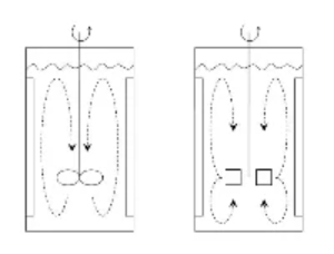
Impellers can be designed to impart various flow characteristics to pump or tank media. Impeller flow designs can take on three distinct types: axial, radial, and mixed. Because centrifugal pumps are also classified in this manner, the impeller selection depends upon matching the pump's flow characteristic to that of the impeller.
- Axial flow impellers move media parallel to the impeller.
- Radial flow impellers move media at right angles to the impeller itself.
- Mixed flow impellers have characteristics of both axial and radial flow. They may move media at an angle which is different from right angle radial flow.

Flow direction of three different pumps/impellers.
Image credit: Globalspec
Impeller Design
Impellers can be broadly classified into two different designs: open and closed. The information below describes these two designs, their respective advantages and disadvantages, and application considerations.
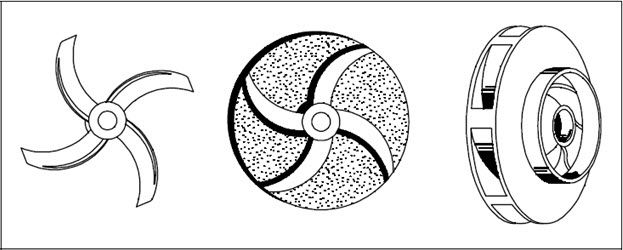
Three impeller designs: (l to r) open, semi-closed, and enclosed (shrouded).
Image credit: TechTransfer
Open Design
Open impellers simply consist of a series of vanes attached to a central "hub" designed to be fitted to a shaft. By fitting the vane ends very close to the pump casing, the open impeller is able to prevent large amounts of fluid or gas from recirculating back through the eye.
A major drawback to open impellers results from the tight vane/casing tolerances required to maintain efficiency. As temperature increases, shafts are known to increase in diameter as well as length (approximately 0.001 inches both ways per inch of shaft for every 100° F increase over ambient temperature). Therefore, a typical centrifugal heat transfer pump operating at 600° F would experience a shaft diameter increase large enough to force the impeller vanes to make contact with the casing, causing sparks and damage to the impeller. (While the casing may also increase in size due to ambient heat, it is often manufactured using different materials than the impeller and therefore may expand at different or unpredictable rates.) For this reason, open impellers are not used in oil and gas applications, as sparks within the impeller would be likely to cause a catastrophic explosion. While open impellers may be manufactured using soft materials to prevent sparks, these materials are typically unsuitable for the abrasive media pumped in oil and gas applications.
The table below describes other advantages and disadvantages of open impeller designs.

Closed Design
Closed impellers feature two solid plates attached to both sides of the blades. After the impeller media enters the eye and makes its way through the vanes it is drawn into a nozzle and expelled. Because closed impellers have no need for vane/casing tolerance consideration, their efficiency results from the use of wear rings to prevent media from being recirculated back to the eye.
As shown in the graph below, closed impellers (dark blue line) are more efficient than open designs (light blue line) and are much more suitable for explosive environments. Because the impeller is closed it is more difficult to access for routine maintenance, however; because closed impellers actually require more maintenance due to the need to periodically replace wear rings, they carry higher maintenance costs but are slightly cheaper to run over time regardless of this fact.
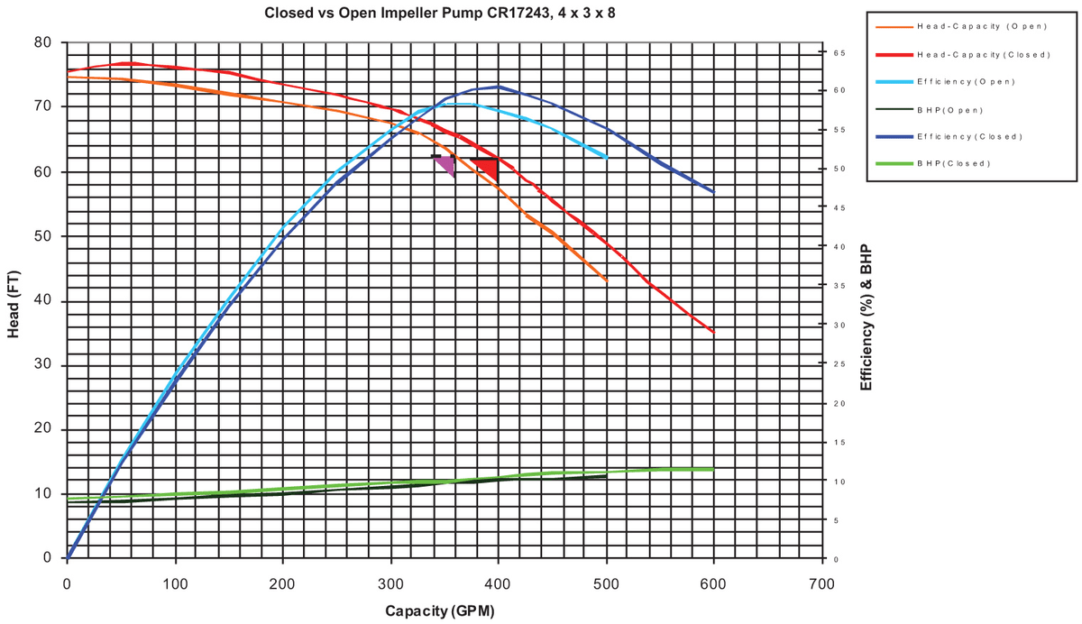
Comparison of closed vs. open impellers. (For larger image, click on Pump-Zone link below.)
Image credit: Pump-Zone
The table below lists advantages and disadvantages of enclosed impellers.

Standards
Impellers may be manufactured, tested, and used based on various industry standards. While standards related to centrifugal pumps and agitation tanks often cover use of impellers, some standards — such as those listed below — are more directly relatable to impellers.
- AMCA 99-2412 -- Impeller diameters for centrifugal fans
- AICHE E-30 -- Impeller-type mixing equipment
Artison is a supplier of aerospace components; Products include impeller, turbine, combustion chamber, fastener, etc.
If you have any questions or needs, please contact us. Here is our contact information:
Price Inquiry:sales.lily@superalloyparts.com
Technical Support:eng.daisy@superalloyparts.com
Quality Control:qc.jason@superalloyparts.com
